


I was looking for some write ups or pictures of none creeping manifolds and stumbled on this.
You are right about the angle of the wastegate, however the explanation isnt quite right.
There is no difference between 'built up pressure' and 'flow pressure', there is just 'pressure' and 'flow'.
Im gonna see if i can sort this out once and for all.
\begin{lecture}
First lets talk about pressure.
As the engine runs, it pumps exhaust gasses into the manifold. The pressure in the manifold is created by the restriction of the turbo. The higher the pressure inside the manifold, the more gas can force itself out through the turbo. The pressure in the manifold will increase until it reaches a point where the amount of gas leaving the manifold is equal to the amount of gas entering the manifold.
When we have reached our deisred boost pressure we open the wastegate to provide an alternate exit for this gas as we dont want any more energy going to the turbo. When the wastegate opens, some of the gas in the manifold will leave via this new route. The smaller the restriction in the wastegate route, the more gas will leave by this path.
Now we can talk about flow.
I mentioned before that we built up pressure in the manifold by making it harder for the gas to leave. This happens when you take away some energy from the moving gas, since we have taken something away in order for everything to balance out we have to put it back in somewhere ie. we have to push the gas harder to make it flow.
There are several ways we can take energy away from our moving gas. The one we discussed before was the turbo. The turbo is taking away some of the energy stored in our fast moving gas and using it to spin the turbine. Other places this happens is in friction as the gas rubs against the walls of the pipe, and friction losses in turbulence if we make the gas flow over something uneven or through a small hole.
We want to make the restriction in the wastegate route as low as possible, so we can get as much gas as possible to go out this way. We do this by making sure there are not many things which are taking energy away from our gas, ie. no turbos, no sudden changes in direction, no small diameter pipes, and no uneven bits which make turbulence.
And this is where we come to the 'design' side of things. The first section of the wastegate route is arguably the most important, because if we cock up this bit then it doesnt matter how beautiful everything looks further down the path. This rather important 'beginning' bit is the junction where the wastegate path splits off from the rest of the manifold.
Before we move on there is one last thing to mention: boundary layers. Unfortunately this may be a bit tricky without pictures, but I will do my best.
A boundary layer is the layer of fluid near to a bounding surface. For pipe work this bounding surface is usually going to be the wall of the pipe. Whenever you have fluid (in this case our exhaust gas) flowing through a pipe a boundary layer forms at the wall. This boundary layer moves slower than the rest of the gas in the pipe as it has to deal with the friction from rubbing on the pipe, and turbulence generated by any imprefections. The end result of this boundary layer is that the amount of gas we can flow through the pipe is slightly less than we would expect since the boundary layer has effectively reduced the diameter of our pipe slightly.
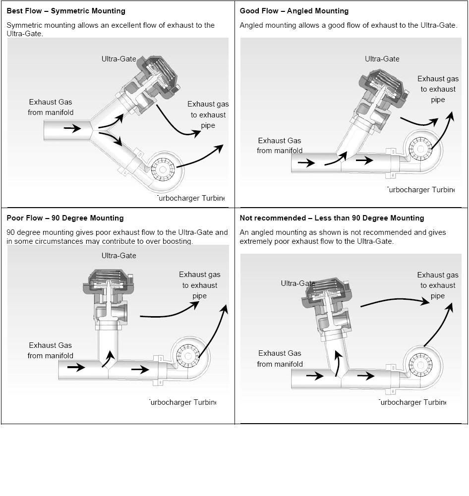
And now the pretty picture from the other thread:
Option 1:
Best.
In this situation the gas doesnt have to make much of a change in direction to get to the wastegate. The flow path is nice and even, there will be minimal energy loss as the gas takes the route to the wastegate. The boundary layer at the Y junction will be more or less the same as the boundary layer in the straight pipe. As a result the gas going down this path dooesnt need to be pushed very hard, so lots of gas will go to the wastegate instead of to the turbo. Just what we were after.
Option 2:
Acceptable.
To get the the wastegate the gas does have to make a change in direction and the boundary layer here is going to be a little different. The gas is coming from the left and heading to the right, and as it starts to head down the wastegate path it overshoots the corner a little. This creates a little spot just on that corner where the boundary layer is a bit bigger, and the effective diameter of the pipe is a bit smaller.
Remembering what we said before about smaller pipes presenting more restriction, we can see that this is going to have slightly more resistance to the gas flow than Option 1. The end result is that a little bit less gas will take our wastegate route and a little bit more will take our turbo route: our wastegate just became a little bit less efficient.
This image shows flow through an intercooler. See in the bottom left where the gas coming in from the charge piping overshoots the corner and creates a 'bubble' of swirling gas which goes nowhere
Option 3:
Not so good.
Here the gas which is going to flow to the wastegate has to make a reasonable change in direction. The gas is going to overshoot the corner just like it did in option 2, but this time it will go further. The 'bubble' of slow moving gas will be bigger and the effective diameter of our pipe will be smaller. We have more restriction and reduced flow: less gas is able to take our wastegate route.
Option 4:
Rubbish.
Same principles as before but even worse for flow. Gas has to make a big change in direction to go down our wastegate route. The overshoot on the corner will be huge, making a really big bubble of slow moving gas on the corner. The effective diameter of our pipe has been reduced significantly and the flow to our wastegate is reduced also. This style of wastegate route is unlikely to be able to flow enough gas to hold our target boost pressure as there is not a big enough difference between the restiction provided by the turbo and the restriction provided by the wastegate route.
So what can we do about it?
We can attempt to rescue a poorly designed manifold by fitting a large wastegate. By making the wastegate piping really big we can compensate for the reduction in effective pipe diameter created by the boundary layer in options 3 and 4. This does work to a certain extent though you will find your self having to buy much more expensive parts.
We can also try to reduce other sources of energy loss in the wastegate route by making the down pipe after the wastegate valve bigger, or by reducing the number of tight bends the down pipe has to make.
One other thing to note is where turbo sizing comes in to this. The bigger your turbo is, the less of a restriction it presents to the exhaust gas (this is where your power increase comes from when you put a bigger turbo on). This means that all of the design issues mentioned above become even more critical because the wastegate must be super efficient to get enough gas flow away from the turbo.
This is part of the reason why car manufacturers get away with really horrible looking wastegate plumbing, because the factory turbo is so small it presents a large restriction and the wastegate doesnt need to be all that efficient to still recieve adequate gas flow.
And there we have it. That is about as best as I can explain it. If I find some decent pictures I will add them to the post.
anymore input is welcomed.
I see my manifold is option 3, straight 90.


 Reply With Quote

Bookmarks