


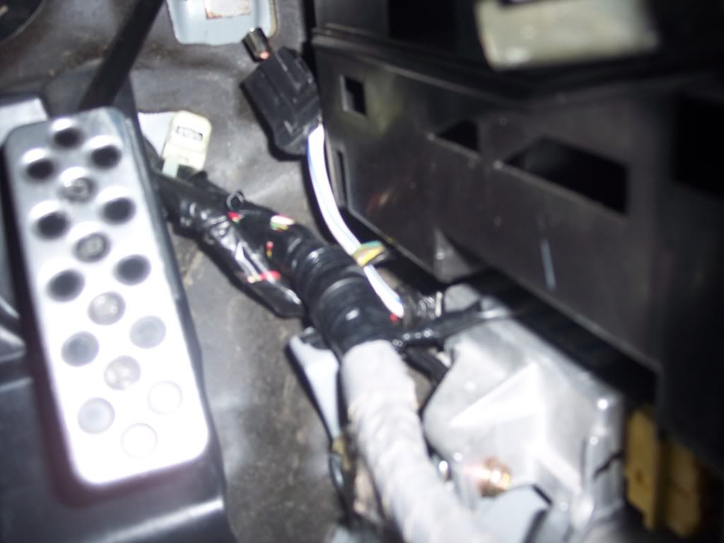
So first thing I did was go inside the car and run the new wiring harness threw the location of the stock wiring harness. Under the carpet footboard for the gas pedal. Then pulled the wire out into the engine bay and up to the eps rack
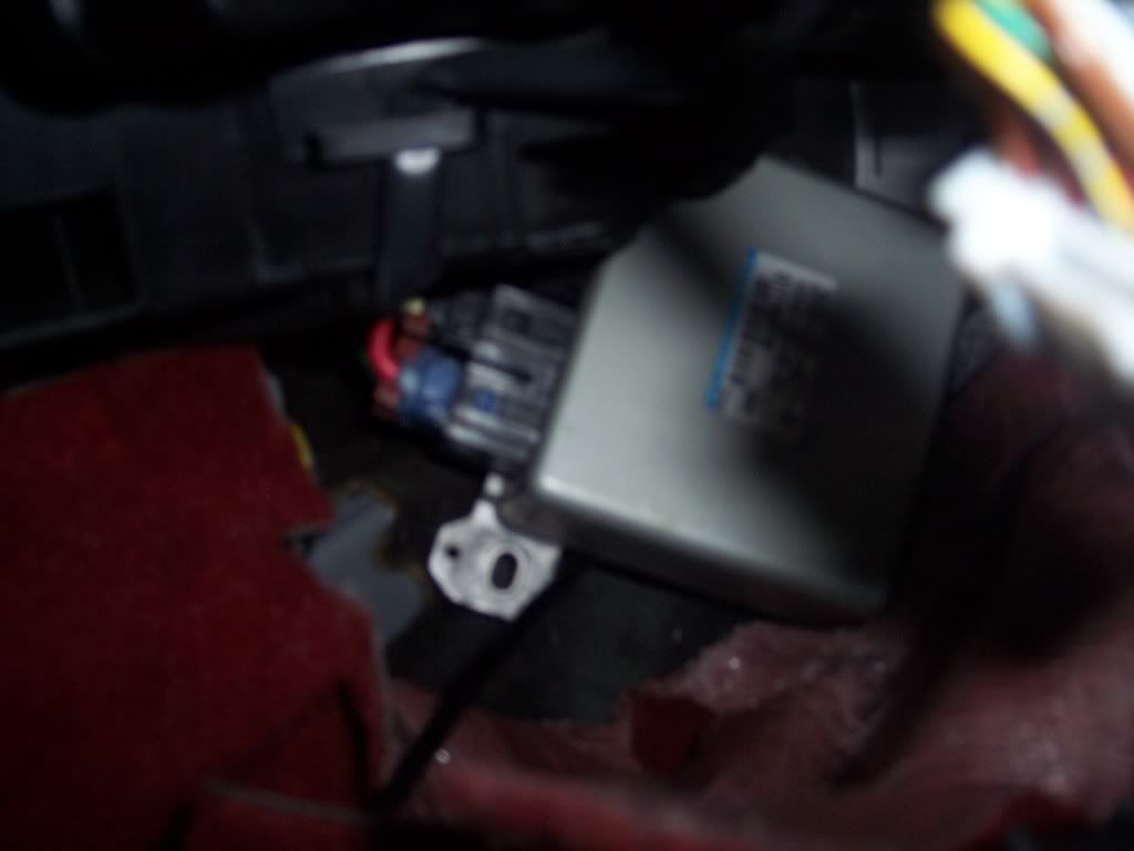
Now I mounted my box and plugged it in
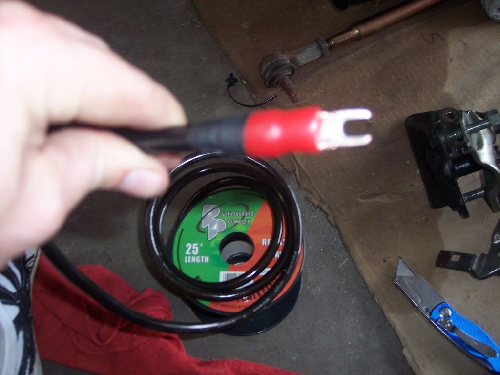
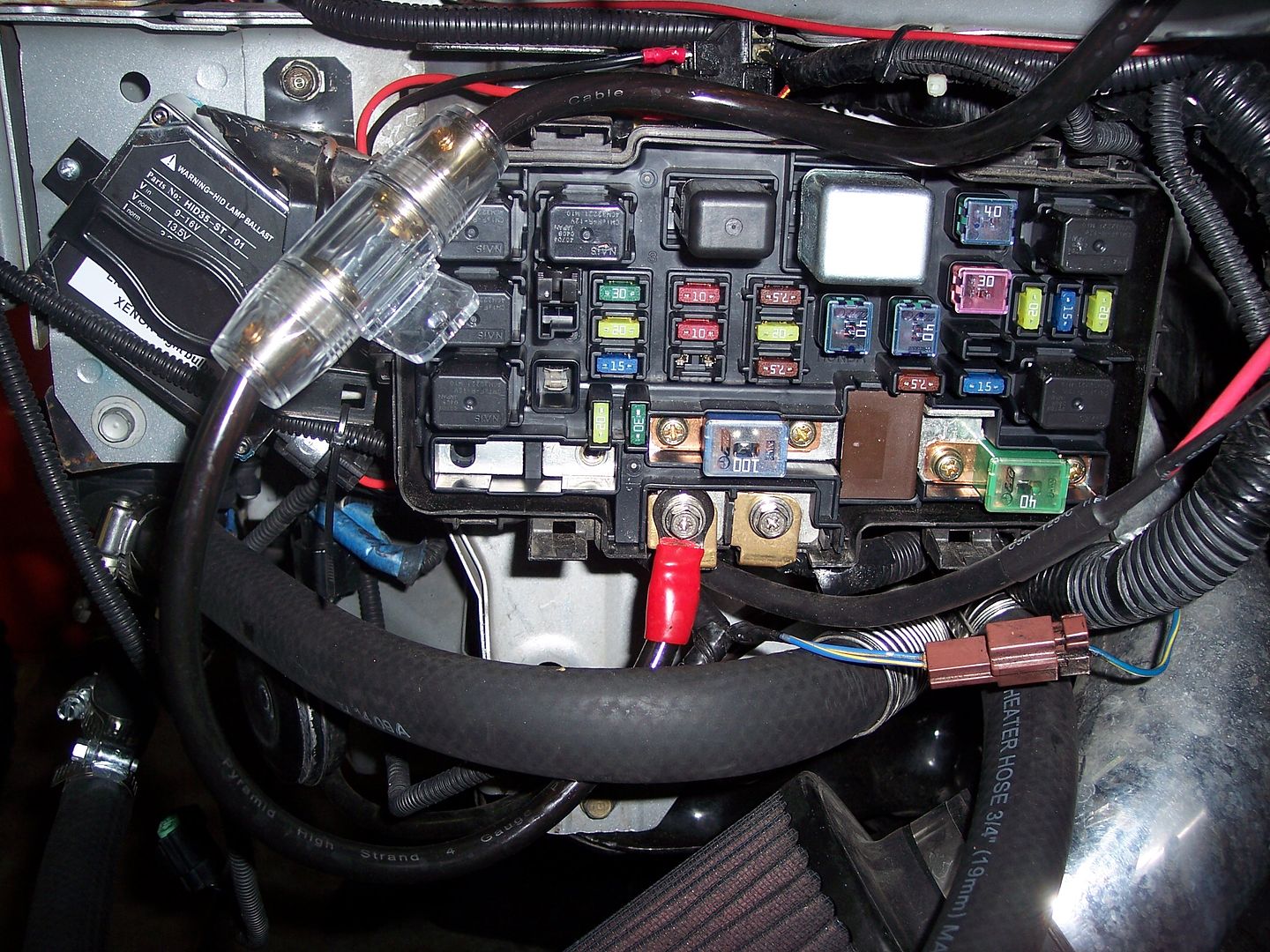
But we need power! For this I made a custom plug into the factory plug and ran a power wire out the fender to my fuse box. You can either go to the fuse box like I did or go to the battery like Loza did. I went to the fuse box because I relocated both box and battery and my box was closer!
and here is where I went into the fuse box. I decided to add a inline fuse. I used the power source on the left which is coming straight from the batter. So if you wanted you go also go straight to the battery instead of the fuse box. But for me my fuse box is closer than my battery.
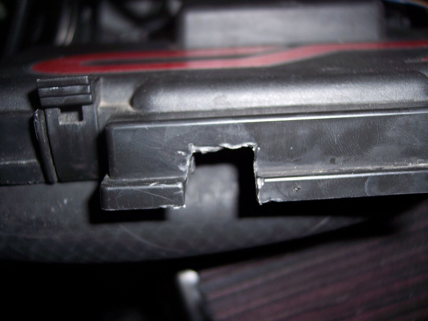
I then cut a small opening for the cable on the lid
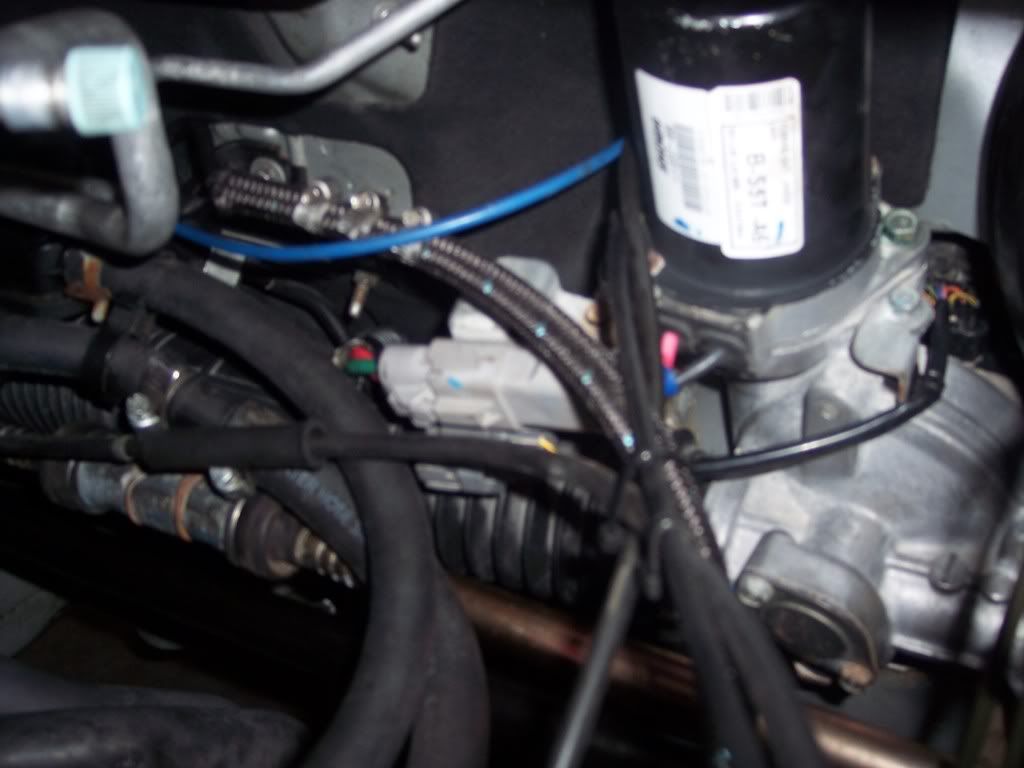
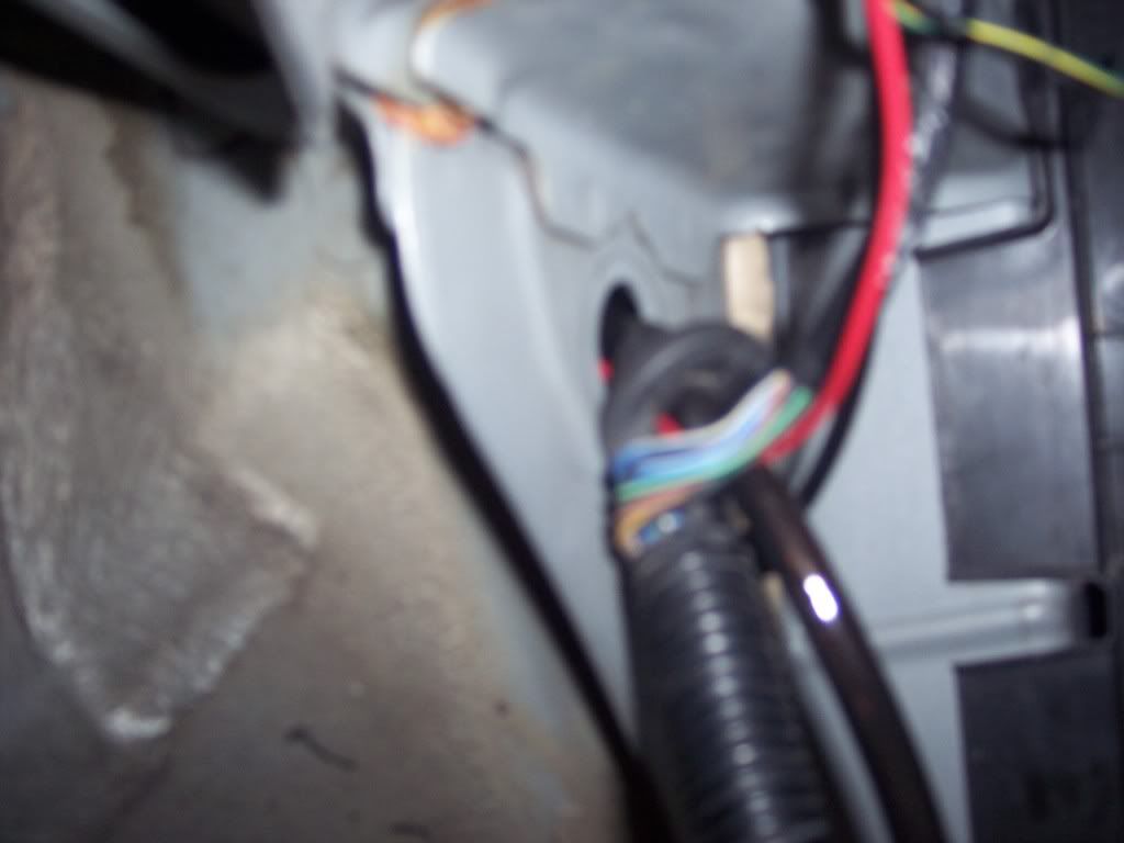
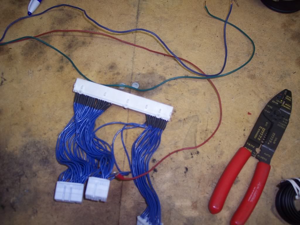
Now onto the ECU wiring! You only need to add three wires to the new EPS. Engine RPM, Vehicle Speed, and constant power!
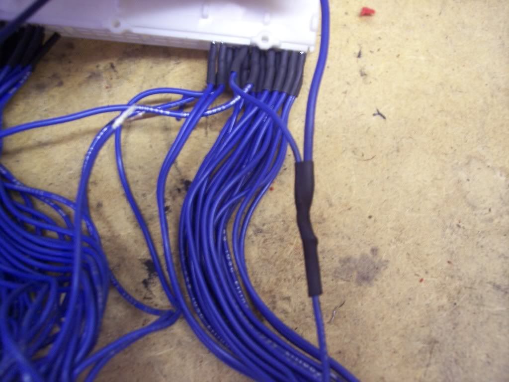
I tapped into the hondata jumper harness using three different colored wires to identify each one!
here I tap into the lines
Blue White goes to pin A18 VSS sensor (vehicle speed sensor located in tranny)
Solid Blue goes to E26 NEP (Engine RPM or Engine Speed Sensor)
Yel goes to pin E9 IGN power (this is IGN to let the BCU know when engine is running)
02-06 ECU diagrams are the same. refer to Hondata for ECU pin out.
http://www.hondata.com/help/kmanager/
Reference > ECU connectors
Connector A (2p)
THICK blue/white is +power for EPS system 60A fused
THICK BLACK is - PG Power ground to chassis

 Reply With Quote

Bookmarks